DS1302 RTC Drivers for STM32 Part 2
Checkout Part 1 to understand inner workings and interface of DS1302
Setup delay_us
You need to first write a delay_us funtions which can do blocking microsecond delays. We need to write our own because STM32CubeHal doesnt not have a microsecond delay.
void delay_us(uint32_t microseconds){
    // Delay code
}
Driver Programming
Init
typedef struct{
    GPIO_TypeDef* port;
    uint16_t pin;
}GpioPin;

typedef struct{
    GpioPin CE_Pin;
    GpioPin IO_Pin;
    GpioPin SCLK_Pin;
}DS1302_HandelTypeDef;
The struct GpioPin represents a single GPIO pin with its Port and Pin number. We take three of these GpioPin to store CE, IO and SCLK pins for DS1302 and call it a struct DS1302_HandelTypeDef. We will be passing this struct to all the funtions of ds1302 so they can access the corresponding pin.
Following is a example initialisation configuration for DS1302_HandelTypeDef.
DS1302_HandelTypeDef rtc = {
    .CE_Pin = {GPIOA, GPIO_PIN_9},          // CE -> PA9
    .SCLK_Pin = {GPIOB, GPIO_PIN_10},       // SCLK -> PB10
    .IO_Pin = {GPIOA, GPIO_PIN_8}           // IO -> PA8
};
Now Lets write a init funtion which will make all the pins as output, It has to be called before using any other funtion.
void ds1302_init(DS1302_HandelTypeDef* handel){
    HAL_GPIO_WritePin(handel->IO_Pin.port, handel->IO_Pin.pin, GPIO_PIN_RESET);
    HAL_GPIO_WritePin(handel->SCLK_Pin.port, handel->SCLK_Pin.pin, GPIO_PIN_RESET);
    HAL_GPIO_WritePin(handel->CE_Pin.port, handel->CE_Pin.pin, GPIO_PIN_RESET);

    GPIO_InitTypeDef gpioinit = {
        .Pin = handel->IO_Pin.pin,
        .Mode = GPIO_MODE_OUTPUT_PP,
        .Pull = GPIO_NOPULL,
        .Speed = GPIO_SPEED_FREQ_LOW
    };

    HAL_GPIO_Init(handel->IO_Pin.port, &gpioinit);

    gpioinit.Pin = handel->CE_Pin.pin;
    HAL_GPIO_Init(handel->CE_Pin.port, &gpioinit);

    gpioinit.Pin = handel->SCLK_Pin.pin;
    HAL_GPIO_Init(handel->SCLK_Pin.port, &gpioinit);
}
In this code, we first RESET all three pins and then configure them for GPIO Output one by one. You just have to pass address of DS1302_HandelTypeDef, eg. ds1302_init(&rtc).
Data input and output
Now lets discuss how can we talk to ds1302, in other words how to do I/O. If you recall from part 1, the I/O involves following steps.
- Set the
CEpin high to initiate data transfer - Start to produce clock signal on
SCLKpin. - First MCU writes the first byte which is the address it want to communicate.
- If MCU wants to write, send the next byte which is the data.
- If MCU wants to read, set its pin in input mode and read the coming data from DS1302.
First lets how to set the CE and produce clock on SCLK.
void ds1302_iotest(DS1302_HandelTypeDef* handel){
    // Start the communication by setting CE HIGH
    HAL_GPIO_WritePin(handel->CE_Pin.port, handel->CE_Pin.pin, GPIO_PIN_SET);

    // Send the address phase
    for(int i=0; i<8; i++){
        HAL_GPIO_WritePin(handel->SCLK_Pin.port, handel->SCLK_Pin.pin, GPIO_PIN_RESET);
        Delay_us(2);
        HAL_GPIO_WritePin(handel->SCLK_Pin.port, handel->SCLK_Pin.pin, GPIO_PIN_SET);
        Delay_us(2);
    }

    // DATA io phase
    for(int i=0; i<8; i++){
        HAL_GPIO_WritePin(handel->SCLK_Pin.port, handel->SCLK_Pin.pin, GPIO_PIN_RESET);
        Delay_us(2);
        HAL_GPIO_WritePin(handel->SCLK_Pin.port, handel->SCLK_Pin.pin, GPIO_PIN_SET);
        Delay_us(2);
    }

    // RESET SCLK and bring to rest state
    HAL_GPIO_WritePin(handel->SCLK_Pin.port, handel->SCLK_Pin.pin, GPIO_PIN_RESET);

    // Stop the communicate by setting CE low
    HAL_GPIO_WritePin(handel->CE_Pin.port, handel->CE_Pin.pin, GPIO_PIN_RESET);
    Delay_us(2);
}
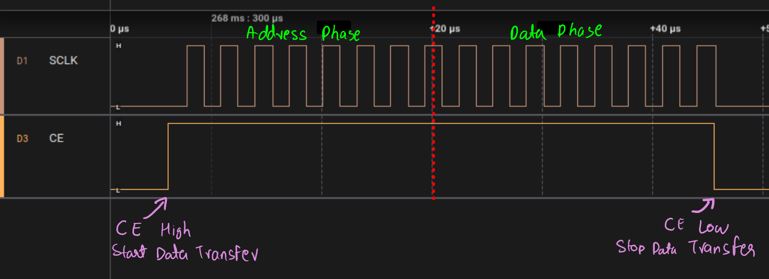
Now If you hookup to logic analyser and you should be able to see following.
We can extend above code to write or read from ds1302.
Write
Along with the DS1302_HandelTypeDef we will also pass two uint8_t ie. address and the data. At each clock pulse we will set the I/O pin high or low based on the data bit.
To get a specific bit at an index we can use following macro
#define GET_BIT(value, bit) (((value) >> (bit)) & 0x01)
This is the code to write a byte to given address
void ds1302_writeByte(DS1302_HandelTypeDef* handel, uint8_t data, uint8_t address){
    HAL_GPIO_WritePin(handel->CE_Pin.port, handel->CE_Pin.pin, GPIO_PIN_SET);

    // Send the address
    for(int i=0; i<8; i++){
        HAL_GPIO_WritePin(handel->IO_Pin.port, handel->IO_Pin.pin,
                            GET_BIT(address, i) ? GPIO_PIN_SET : GPIO_PIN_RESET);
        Delay_us(2);
        HAL_GPIO_WritePin(handel->SCLK_Pin.port, handel->SCLK_Pin.pin, GPIO_PIN_SET);
        Delay_us(2);
        HAL_GPIO_WritePin(handel->SCLK_Pin.port, handel->SCLK_Pin.pin, GPIO_PIN_RESET);
        Delay_us(2);
    }

    // Send the data
    for(int i=0; i<8; i++){
        HAL_GPIO_WritePin(handel->IO_Pin.port, handel->IO_Pin.pin,
                            GET_BIT(data, i) ? GPIO_PIN_SET : GPIO_PIN_RESET);
        Delay_us(2);
        HAL_GPIO_WritePin(handel->SCLK_Pin.port, handel->SCLK_Pin.pin, GPIO_PIN_SET);
        Delay_us(2);
        HAL_GPIO_WritePin(handel->SCLK_Pin.port, handel->SCLK_Pin.pin, GPIO_PIN_RESET);
        Delay_us(2);
    }

    HAL_GPIO_WritePin(handel->CE_Pin.port, handel->CE_Pin.pin, GPIO_PIN_RESET);
    HAL_GPIO_WritePin(handel->SCLK_Pin.port, handel->SCLK_Pin.pin, GPIO_PIN_RESET);
    HAL_GPIO_WritePin(handel->IO_Pin.port, handel->IO_Pin.pin, GPIO_PIN_RESET);
    Delay_us(2);
}
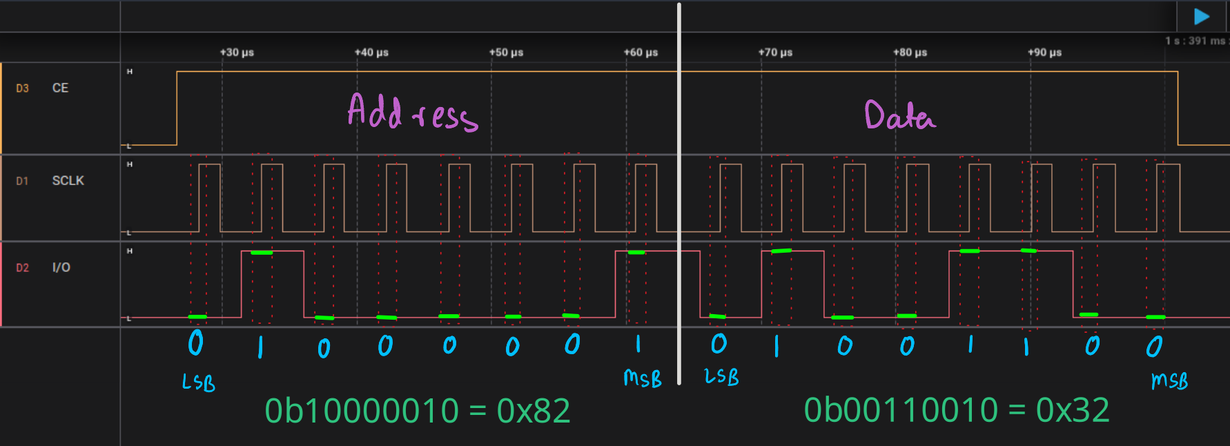
According to datasheet.
For data inputs, data must be valid during the rising edge of the clock and data bits are output on the falling edge of clock
That means we need to write data at rising edge and read data at falling edge of SCLK. Lets take an example where we write 0x32 to address 0x82. So the code would be ds1302_writeByte(&rtc, 0x32, 0x82). Following is the output of data analyser
Read
To read, first we pass the address then read the data sent by ds1302. To do as such we need to toggle input and output mode of the IO pin midway. Here are two funtions to switch the pin modes.
void ds1302_enableWriteMode(DS1302_HandelTypeDef* handel){
    GPIO_InitTypeDef gpioinit = {
        .Pin = handel->IO_Pin.pin,
        .Mode = GPIO_MODE_OUTPUT_PP,
        .Pull = GPIO_NOPULL,
        .Speed = GPIO_SPEED_FREQ_LOW
    };
    HAL_GPIO_Init(handel->IO_Pin.port, &gpioinit);
}

void ds1302_enableReadMode(DS1302_HandelTypeDef* handel){
    GPIO_InitTypeDef gpioinit = {
        .Pin = handel->IO_Pin.pin,
        .Mode = GPIO_MODE_INPUT,
        .Pull = GPIO_NOPULL,
    };
    HAL_GPIO_Init(handel->IO_Pin.port, &gpioinit);
}
For read operation, we cant send the address directly, we need to make the first bit high which makes it read operation. After sending the address, just read the state of IO pin at falling edge of SCLK. Here is the code.
uint8_t ds1302_readByte(DS1302_HandelTypeDef* handel, uint8_t address){
    // Start the communication
    HAL_GPIO_WritePin(handel->CE_Pin.port, handel->CE_Pin.pin, GPIO_PIN_SET);

    address |= 0x01;    // Make it read enabled
    // Send the address
    for(int i=0; i<8; i++){
        HAL_GPIO_WritePin(handel->IO_Pin.port, handel->IO_Pin.pin,
                            GET_BIT(address, i) ? GPIO_PIN_SET : GPIO_PIN_RESET);
        Delay_us(2);
        HAL_GPIO_WritePin(handel->SCLK_Pin.port, handel->SCLK_Pin.pin, GPIO_PIN_SET);
        Delay_us(2);
        HAL_GPIO_WritePin(handel->SCLK_Pin.port, handel->SCLK_Pin.pin, GPIO_PIN_RESET);
        Delay_us(2);
    }

    ds1302_enableReadMode(handel);  // Transition IO pin to input mode

    // Read the data byte
    uint8_t data = 0;
    for(int i=0; i<8; i++){
        // flip the i'th bits high if pin is high
        if(HAL_GPIO_ReadPin(handel->IO_Pin.port, handel->IO_Pin.pin) == GPIO_PIN_SET){
            data |= (1 << i);
        }
        Delay_us(2);
        HAL_GPIO_WritePin(handel->SCLK_Pin.port, handel->SCLK_Pin.pin, GPIO_PIN_SET);
        Delay_us(2);
        HAL_GPIO_WritePin(handel->SCLK_Pin.port, handel->SCLK_Pin.pin, GPIO_PIN_RESET);
        Delay_us(2);
    }

    HAL_GPIO_WritePin(handel->CE_Pin.port, handel->CE_Pin.pin, GPIO_PIN_RESET);
    HAL_GPIO_WritePin(handel->SCLK_Pin.port, handel->SCLK_Pin.pin, GPIO_PIN_RESET);
    HAL_GPIO_WritePin(handel->IO_Pin.port, handel->IO_Pin.pin, GPIO_PIN_RESET);
    Delay_us(2);
    ds1302_enableWriteMode(handel);     // Reset IO pin to output mode
    return data;
}
Lets take an example where we read from the address 0x82. call funtions ds1302_readByte(0x82)