DS1302 RTC Drivers for STM32 Part 1
Introduction
The DS1302 is a Real-Time Clock (RTC) IC used to keep track of time and date. It has the capability to store data such as seconds, minutes, hours, day, date, month, and year. The DS1302 can be interfaced with microcontrollers using a simple serial communication protocol (SPI-like but with slight differences). It also includes 31 bytes of static RAM for temporary data storage.
Interface with module
Pinout
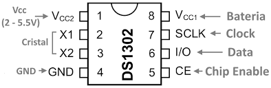
Above is the pinout of DS1302. This is description of each pin.
- Vcc2: This is the main power supply which you connect to any 3.3v or 5v power source.
- Vcc1: Connect a flat lithium sound button cell which powers the low power operation i.e. keeping the clock ticking.
- X1/X2: Connect any 32.768kHz Quartz Crystal.
- GND: Just a ground
- CE: When Chip Enable pin is set high, it initiates the data transfer. It is kept high till the data transfer is being done.
- I/O: This pin is used to send and receive data.
- SCLK: The microcontroller generates clock on this line, this clock is used to synchronise the MCU and DS1302.
Communication
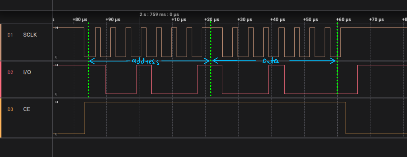
Communication happens in following step.
- Set the
CEpin high to initiate data transfer - Start to produce clock signal on
SCLKpin. - First MCU writes the first byte which is the address it want to communicate.
- If MCU wants to write, send the next byte which is the data.
- If MCU wants to read, set its pin in input mode and read the coming data from DS1302.
Addressing
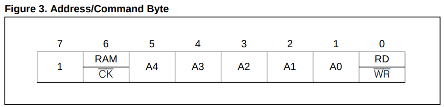
The address space in ds1302 is divided into two parts.
- Clock/Calendar: If the
bit 6is set to low, it allows you to access Clock/Calendar space. This is where datetime information is stored. - RAM: If the
bit 6is set to high, it allows you to access the RAM space. DS1302 provides your 31 bytes of storage where you can write or ready any personal data. It is a non-volatile storage space useful to store some configuration data.
The bit 7 is always set to high, The bit 0 lets your specify read or write operation, write operation when set to low and read operation when set to high. Bit 1-5 used to specify address from 0-31.
Clock/Calendar address
There are only 7 bytes useful to read or write in Clock/Calendar address space.
- Byte -> Second
- Byte -> Minutes
- Byte -> Hour
- Byte -> Date
- Byte -> Month
- Byte -> Day
- Byte -> Year
Lets try to calculate some address ourself:
- How to read Month data
Month address -> 4 -> 0b00100

               B7  C/R  A4  A3  A2  A1  A0  R/W
Address Byte:   1   0   0   0   1   0   0    1
- How to write year data
Year address -> 6 -> 0b00110

               B7  C/R  A4  A3  A2  A1  A0  R/W
Address Byte:   1   0   0   0   1   1   0    0
Ram address
You can access to all 31 bytes to read and write data from the RAM address space
Lets try to calculate some address ourself:
- How to read from address 0
Month address -> 0 -> 0b00000

               B7  C/R  A4  A3  A2  A1  A0  R/W
Address Byte:   1   1   0   0   0   0   0    1
- How to write to address 31
Year address -> 30 -> 0b11110

               B7  C/R  A4  A3  A2  A1  A0  R/W
Address Byte:   1   1   1   1   1   1   0    0
Clock/Calendar data
Data representation of DS1302 is rather different, I though it just stored the numbers directly in binary but it rather uses a different approach called BCD(binary-coded decimal) which first splits a decimal number into its individual digits and convert each decimal digit to binary using 4 bits.
Here is an example for BCD
Decimal Number: 56
Binary Value:   00111000

Decimal Digit:     5       6
BCD Value:        0101    0110
This is the complete Clock/Calendar datamap I took from the DS1302 datasheet. Lets go though them one by one
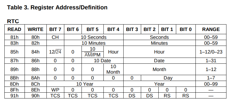
Seconds
| BIT 7 | BIT 6 | BIT 5 | BIT 4 | BIT 3 | BIT 2 | BIT 1 | BIT 0 | RANGE |
|---|---|---|---|---|---|---|---|---|
| CH | 10 Second | Seconds | 00-59 | |||||
Bit 7of second isCH(Clock Halt), when this bit is set high the clock is set to halt and stops ticking and continue ticking when you set low.Bit 6-4is the BCD representation of the tens digit of the second value eg. 5 in 56, 3 in 32. Range:0-5Bit 3-0is the BCD representation of the ones digit of the second value eg. 6 in 56, 2 in 32. Range:0-9
Example: Data value for 56 second would be 0b01010110
Minutes
| BIT 7 | BIT 6 | BIT 5 | BIT 4 | BIT 3 | BIT 2 | BIT 1 | BIT 0 | RANGE |
|---|---|---|---|---|---|---|---|---|
| 10 Minutes | Minutes | 00-59 | ||||||
Bit 7is left empty i.e. logic 0Bit 6-4is the BCD representation of the tens digit of the minutes value eg. 5 in 56, 3 in 32. Range:0-5Bit 3-0is the BCD representation of the ones digit of the minutes value eg. 6 in 56, 2 in 32. Range:0-9
Hour
Hour is bit tricky because it operates in two modes i.e. 12 and 24 hrs.
| BIT 7 | BIT 6 | BIT 5 | BIT 4 | BIT 3 | BIT 2 | BIT 1 | BIT 0 | RANGE |
|---|---|---|---|---|---|---|---|---|
| 12/24 | 0 | 10 | Hour | Hour | 0-23 | |||
| AM/PM | 1-12 | |||||||
- If
Bit 7is high then 12 hour mode selectedBit 5represent the meridiem. PM if High and AM if Low.Bit 4is the BCD representation of the tens digit of the minutes value. Range:0-1Bit 3-0is the BCD representation of the ones digit of the minutes value. Range:0-9
- If
Bit 7is low then 24 hour mode selectedBit 5-4is the BCD representation of the tens digit of the minutes value. Range:0-2Bit 3-0is the BCD representation of the ones digit of the minutes value. Range:0-9
Bit 6unused bit, so should set to low Example:
Time: 7:45 PM
Hour: 7, Mode: 12hrs, Meridiem: PM

      Mode  B6   Mer  H10   -----H1------
Data:   1    0    1    0    0   1   1   1


Time: 17:46
Hour: 17, Mode: 24hrs

      Mode  B6   ---H10--   -----H1------
Data:   0    0    1    1    0   1   1   0
Date
| BIT 7 | BIT 6 | BIT 5 | BIT 4 | BIT 3 | BIT 2 | BIT 1 | BIT 0 | RANGE |
|---|---|---|---|---|---|---|---|---|
| 0 | 0 | 10 Date | Date | 1-31 | ||||
Bit 7-6unused leave empty i.e. logic 0Bit 5-4is the BCD representation of the tens digit of the Date value. Range:0-3Bit 3-0is the BCD representation of the ones digit of the Date value. Range:0-9
Month
| BIT 7 | BIT 6 | BIT 5 | BIT 4 | BIT 3 | BIT 2 | BIT 1 | BIT 0 | RANGE |
|---|---|---|---|---|---|---|---|---|
| 0 | 0 | 0 | 10 month | month | 1-12 | |||
Bit 7-5unused leave empty i.e. logic 0Bit 4is the BCD representation of the tens digit of the month value. Range:0-1Bit 3-0is the BCD representation of the ones digit of the month value. Range:0-9
Day
| BIT 7 | BIT 6 | BIT 5 | BIT 4 | BIT 3 | BIT 2 | BIT 1 | BIT 0 | RANGE |
|---|---|---|---|---|---|---|---|---|
| 0 | 0 | 0 | 0 | 0 | Day | |||
Bit 7-3unused leave empty i.e. logic 0Bit 2-0represent day of the week, range: 1-7
Year
| BIT 7 | BIT 6 | BIT 5 | BIT 4 | BIT 3 | BIT 2 | BIT 1 | BIT 0 | RANGE |
|---|---|---|---|---|---|---|---|---|
| 10 year | year | 00-99 | ||||||
Bit 7-4is the BCD representation of the tens digit of the year value. Range:0-9Bit 3-0is the BCD representation of the ones digit of the year value. Range:0-9
Checkout Part 2 to understand inner workings and interface of DS1302